pixel Melt v1.0.0 Script For After Effect And Premiere
Pixel Melt v1.0.0 Script for Creating Beautiful Stretch Effects for Scene Pixels in After Effects and Premiere
Pixel Melt simulates independent stretching and displacement of pixels. Applicable for various image distortions, including melting simulation or scanlines separation with modulation ability.
This section includes the Pixel Melt version 1.0.0 script for After Effects and Premiere, which is available for download on the site. With the help of this plugin, you can create a beautiful stretch effect for the pixels of the scene. This effect makes for a beautiful and attractive stretch for the pixels in the scene. This plugin allows pixels to be stretched in different directions, allowing for beautiful and attractive effects.
How it works
The Pixel Melt effect treats each image pixel independently. It simulates a process where a velocity and a spreading amount are assigned to each pixel in a given direction according to its brightness. Effect similarly filters the image via processing individual scanlines as in Pixel Stretch, but with a significant difference, as pixels overlap each other while moving independently via their velocities and are not processed sequentially in a cumulative manner.
You have a usual set of curves to map pixel brightness into velocity and spread amount. The melting process is achieved by animating the master intensity or melt step parameter. Stretched pixels are drawn in a solid color or with additional shading.
You can also control the step at which pixels are processed over the scanlines or modulate the starting position, allowing other stylizing qualities. Extras include removing gaps in the output (as this effect is tearing the image), performing additional stretching of the melted image back to its original screen area, or fading the start/end of scanlines.
Parameters guide

- Direction – defines towards which edge the melting and other effects occur.
- Velocity Intensity Source – use a different input layer to determine the velocity of the pixels. This can be thought of as a “velocity mask”. By default, the input image serves as a velocity mask.
- Spread Intensity Source – use a different input layer to control the stretching of the pixels. This can be thought of as a “stretch mask”. By default, the input image serves as a spread mask.
- Pixel Melt Intensity – controls how much melting of pixels is applied. Use this parameter to animate melting simulation over time. At 0%, no melting occurs, and at 100%, melting is at full intensity set by further parameters. In addition to interpolating the Melt Step parameter, it also controls how much fading for the start and end of the screen is applied. Scanline features are not affected by this parameter and work independently.
▽ Pixel
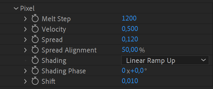
- Melt Step – defines the stage of melting simulation. You can understand it as a multiplier of Velocity and Spread parameters. You can animate the simulation by interpolating this parameter as well. Still, dialing the final melt step of your simulation here might be more handy and animate the process via the main Pixel Melt Intensity parameter. Be careful with dialing too high values with a Spread parameter over 0.25 and using a high Melt Step value. If Melt Step is at its maximum value of 16384 and Spread is 1.0, it means at 100% Pixel Melt Intensity, some pixels might end up of length 16384 pixels, and it’s met with a significant performance dropdown.
- Velocity – defines the maximum shift of pixels derived from its luminosity in a given direction per one melt step and calculated via remapping its brightness intensity via a velocity curve. By default, the brighter the pixel, the faster it moves.
- Spread – defines the maximum stretching of pixels in a given direction per one melt step.
- Spread Alignment – controls how stretched pixels align to their position after applying velocity shift. At 50%, stretched pixels are center aligned to unstretched pixels position. At 0%, stretched pixels appear before and end at the position of unstretched pixels. At 100%, pixels are stretched right from the start of the unstretched pixel.
- Shading – offers you to keep pixels just plain stretched or choose one of the available shading options: Sine Wave, Triangle Wave, Linear Ramp Up or Down.
- Shading Phase – sets the phase of shading in stretched pixels. Animate this parameter for an additional effect.
- Shift – is the contrast value added to the output from velocity curve mapping and is independent from pixel’s brightness. Useful, if you have set the velocity curve to your liking but want to add a constant value to pronounce more melting movement. Since the parameter range is from -1.0 to 1.0, you can set it to move the whole image or some of its pixels in an opposite direction.
▽ Scanline Step

- Melt Step – defines the stage of melting simulation. You can understand it as a multiplier of Velocity and Spread parameters. You can animate the simulation by interpolating this parameter as well. Still, dialing the final melt step of your simulation here might be more handy and animate the process via the main Pixel Melt Intensity parameter. Be careful with dialing too high values with a Spread parameter over 0.25 and using a high Melt Step value. If Melt Step is at its maximum value of 16384 and Spread is 1.0, it means at 100% Pixel Melt Intensity, some pixels might end up of length 16384 pixels, and it’s met with a significant performance dropdown.
- Velocity – defines the maximum shift of pixels derived from its luminosity in a given direction per one melt step and calculated via remapping its brightness intensity via a velocity curve. By default, the brighter the pixel, the faster it moves.
- Spread – defines the maximum stretching of pixels in a given direction per one melt step.
- Spread Alignment – controls how stretched pixels align to their position after applying velocity shift. At 50%, stretched pixels are center aligned to unstretched pixels position. At 0%, stretched pixels appear before and end at the position of unstretched pixels. At 100%, pixels are stretched right from the start of the unstretched pixel.
- Shading – offers you to keep pixels just plain stretched or choose one of the available shading options: Sine Wave, Triangle Wave, Linear Ramp Up or Down.
- Shading Phase – sets the phase of shading in stretched pixels. Animate this parameter for an additional effect.
▽ Scanline Modulation
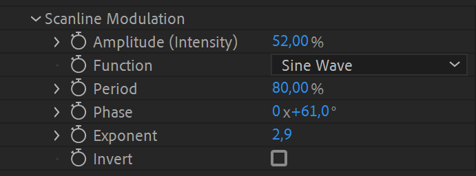
- Amplitude (Intensity) – of scanline modulation given in percentage of scanline length.
- Function – is a math function used to modulate the start of scanlines perpendicularly to the melting direction. Functions available: Sine Wave, Triangle Wave, Linear Ramp Up / Down, 1/2 Phase.
- Period – is a length for function modulating scanlines set in percentage of perpendicular length.
- Phase – defines the start position of modulation’s function.
- Exponent – parameter allows to tweak modulation via power function.
- Invert – flips the chosen function.
▽ Velocity Curve
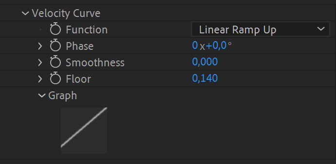
- Function – specifies how pixel brightness maps to its velocity in the set direction. The default function (Linear Ramp Up and the rest of the parameters set to 0) doesn’t move black pixels at all and white pixels by the maximum amount specified by the Velocity parameter (multiplied by Melt Step). Linear Ramp Down is the opposite behavior. The following chart illustrates all the available mappings:
- Phase – offsets the values of velocity curve mapping.
- Smoothness – helpful for smoothly connecting the beginning and the end of discontinuous curves (linear ramps and exponentials) or smoothing out a triangular curve.
- Floor – defines the minimum velocity value.
- Graph* – visualizes the velocity curve mapping for your convenience.
▽ Spread Curve
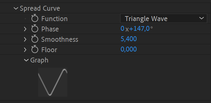
- Function – specifies how pixel brightness (luminosity) maps to its stretching in the set direction. The default function (Linear Ramp Up and the rest of the parameters set to 0) doesn’t stretch black pixels at all and white pixels by the maximum amount specified by the Spread parameter (multiplied by Melt Step). Linear Ramp Down is the opposite behavior. The following chart illustrates all the available mappings:
- Phase – offsets the values of spread curve mapping.
- Smoothness – helpful for smoothly connecting the beginning and the end of discontinuous curves (linear ramps and exponentials) or smoothing out a triangular curve.
- Floor – defines the minimum velocity value.
- Graph* – visualizes the spread curve mapping for your convenience.
▽ Screen
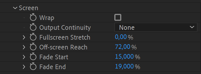
- Wrap – can be enabled for a mode, when pixels of the image don’t fall beyond the visible area, but appear from the other side.
- Output Continuity – is used if you want to remove gaps in the output image. Option “All” removes all gaps, option “All (No Start)” is almost the same, besides leaving alpha blending at the start of each scanline, which might be sometimes useful. Option “Full Alpha Only” fills gaps only between pixels with the full opacity, which creates an interesting glitch effect. Please note, that using this feature also removes any gaps created by using alpha in the input image (which can be used to your advantage).
- Fullscreen Stretch – is an additional post-effect which interpolates visible parts of melting simulation back to the whole screen area.
- Off-screen Reach – gives you the ability to display parts of melting simulation which have fallen beyond the visible screen area.
- Fade Start – sets the percentage of dimming the start of scanlines. At 50% they are half dimmed along its visible scanline length. At 100% fully dimmed. Fade Start/End parameters are interpolated by the main Pixel Melt Intensity parameter.
- Fade End – Sets the percentage of dimming the end of scanlines. The same functionality as for Fade Start, just from the other side.
* The graphs are not available in CC2014 or earlier.

| PLATFORMS | |
| Microsoft Windows | ✓ |
| macOS Intel | ✓ |
| macOS Apple Silicon | ✓ |
| APPLICATIONS | VERSIONS | |
| After Effects | ✓ | CS6 – 2024 |
| Premiere Pro | ✓ | CS6 – 2024 |
| FEATURES | |
| Max. Rendering Resolution | 16384 |
| Multi-Frame Rendering | ✓ |
| Utilizing GPU | ✗ |
After effects templates
Amazing clips to use and help you create your own unique projects from AE templates or to improve the design of your existing broadcasts.
We have a wide range of templates for you to choose from. You can find PowerPoint Video Templates, Motion Graphics Templates, and After Effects Logo Templates, Scripts, Promos, news, fashion, sports, social media, titles…
After Effects Templates, Wedding Templates as well, After Effects Intro Templates, Transitions, Products Promos, Instagram stories, Scripts, Call Titles, Elements 3D, Corporate , and many more.
With After Effects project files, or templates, your work with motion graphics and visual effects will get a lot easier. In short, they are customizable After Effect files, neatly organized and labelled. You can easily change colors, text and other design elements without having to spend time on creating timelines and effects. It’s all there-you just need to customize it to fit your project.
What you waiting for? Hurry up and download the best after effects templates
➡️ ➡️ For more Ready Project Files Templates 😀 😀
➡️ ➡️ For more after effects plugins 😀 😀
System Requirement For adobe after effects

Reviews
There are no reviews yet.